
How Dynamic Pressure Is Measured in Vehicle Wind Tunnels
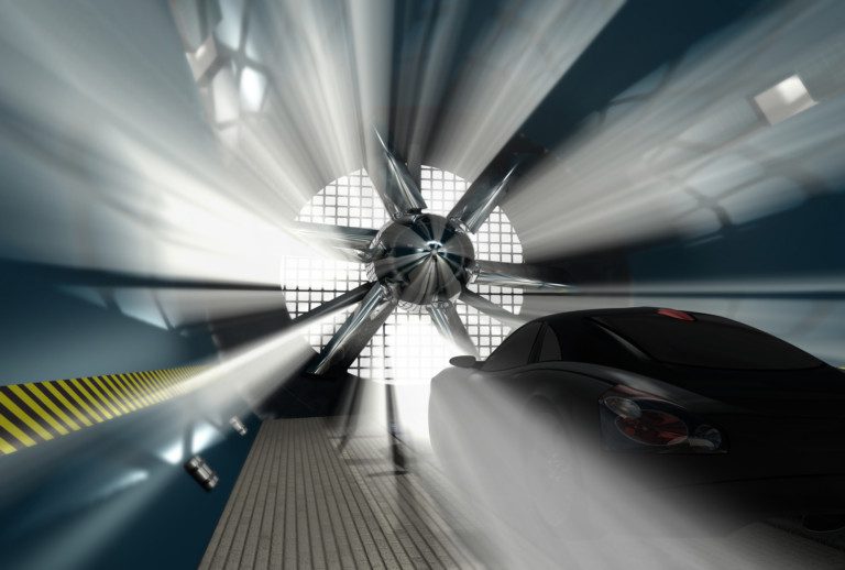
Dynamic pressure is measured as the difference between total pressure and static pressure, using a probe in the flow, a differential pressure sensor, and a data acquisition system that logs the result along with air temperature. Everything else in a vehicle wind tunnel test, from the speed setting to drag and downforce coefficients, depends on getting that one measurement right.
What dynamic pressure is
Dynamic pressure is the kinetic energy of the moving air per unit volume. It sets the speed of the test and normalizes every aerodynamic force and pressure measured on the vehicle.
q = pt − ps = ½ρV²
Here pt is total pressure, ps is static pressure, ρ is air density, and V is velocity. This form holds for incompressible flow, which covers the low subsonic speeds of vehicle testing. Because velocity depends on density, and density depends on temperature and absolute pressure, those two quantities have to be measured too.
How it is measured
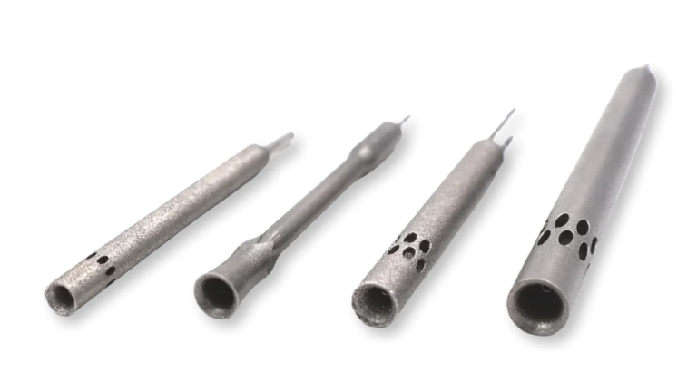
A pitot-static probe or a Kiel probe faces into the flow and senses total pressure at its tip. A static pressure source, either ports on the same probe or a separate reference, senses static pressure. The two pressures are connected through tubing to a differential pressure sensor, which outputs dynamic pressure directly.
A standard pitot tube needs to be aligned with the flow, typically within roughly 5°. Where the flow angle is uncertain, a Kiel probe holds accuracy to roughly 50° depending on its design. Where the flow angle is itself a result you need, such as around wheels, mirrors, or in the wake, a multi-hole probe resolves total pressure, static pressure, and yaw and pitch angles from one position. For a fuller look at probe types, see our post on flow probes for wind tunnel testing.
Sensors used for data logging
Three kinds of sensor feed the data acquisition system in a typical vehicle test.
- Differential pressure transducers read a single dynamic pressure. They suit a reference probe that monitors tunnel speed.
- Electronic pressure scanners read many channels at once, so one scan can capture a multi-hole probe’s ports, a rake, and body surface taps together. They are the standard tool when the number of measurement points is large.
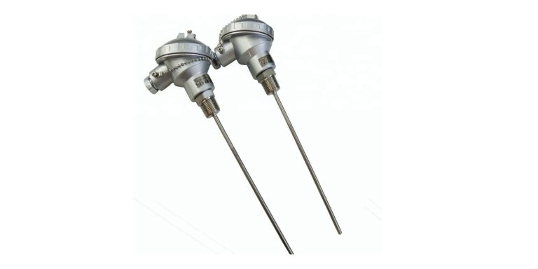
- Thermocouples and RTDs measure air temperature for the density calculation. They are also used on the vehicle itself in cooling, brake, and thermal management tests.
An absolute pressure reading from the tunnel completes the set needed to compute density.
What to specify
| Parameter | Why it matters |
|---|---|
| Pressure range and accuracy (percent of full scale) | Dynamic pressure is a small number at low tunnel speeds, so a range sized too large costs resolution |
| Zero stability over the run | Drift looks the same as a design change in the data |
| Sample rate and averaging time | Turbulent flow needs enough averaging to produce a stable mean |
| Channel count | Set by the number of probe ports, rake tubes, and surface taps in the test plan |
| Output interface | Must match the data acquisition system, commonly USB or Ethernet |
| Probe calibration data | A multi-hole probe is only meaningful through its calibration map across speed and angle |
Three practices protect data quality. Zero the pressure sensors with the tunnel off before each run. Keep tubing as short as the setup allows, because tubing volume slows the response. Keep probes small relative to the test section so they do not disturb the flow they measure.
Instrumentation for your test program
K-Tec Systems supplies flow probes, pressure scanners, and custom thermocouples for automotive and aerospace wind tunnel programs. To discuss the right configuration for your test, contact us at 248-414-4100 or contact@k-tecsystems.com.