How to Calculate True Airspeed from Pitot-Static Data
True airspeed (TAS) is the speed of an aircraft relative to the air mass it is flying through. It is the number that matters for navigation, performance modeling, and aerodynamic analysis. It is also not what a pitot-static system measures directly.
What the pitot-static system measures is a pressure difference. Getting from that pressure difference to true airspeed takes a chain of corrections, and each one depends on a measurement that has its own error budget.
What the pitot-static system actually measures
A pitot tube pointed into the flow senses total pressure. A static port senses the ambient static pressure. The difference between them is dynamic pressure, and dynamic pressure is a function of air density and velocity.
NASA Glenn states the relationship as V = √(2(pt − ps)/ρ), where pt is total pressure, ps is static pressure, and ρ is air density. The airspeed indicator, however, has no way to know the actual density. It is calibrated assuming sea-level standard density, and that assumption is the reason the correction chain exists.
The four airspeeds
Indicated airspeed (IAS) is what the instrument displays. It is the dynamic pressure converted to speed using sea-level standard density, with no other corrections.
Calibrated airspeed (CAS) is IAS corrected for instrument error and position error. Position error comes from the static port not sensing true ambient static pressure because of the local flow around the airframe. The correction varies with angle of attack, configuration, and speed, and it is determined by flight test.
Equivalent airspeed (EAS) is CAS corrected for compressibility. At low Mach numbers the correction is negligible. Above roughly 200 knots or 10,000 feet it becomes significant, because the air compresses in front of the pitot tube and raises the sensed total pressure.
True airspeed (TAS) is EAS corrected for actual air density. The relationship is TAS = EAS / √σ, where σ is the density ratio, the actual air density divided by sea-level standard density (1.225 kg/m³).
Calculating TAS step by step
Start with IAS from the instrument or the air data unit. Apply the position and instrument error corrections from the aircraft’s calibration data to get CAS. For low-speed, low-altitude work, CAS and EAS are close enough to treat as equal. Otherwise apply the compressibility correction.
Then determine the density ratio. Density depends on static pressure and outside air temperature, which is why both are inputs to every air data computer. From pressure altitude and temperature, calculate density altitude, then look up or compute σ. Divide EAS by the square root of σ to get TAS.
For a quick estimate at low altitude, SKYbrary gives the rule of thumb of adding 2% to calibrated airspeed for every 1,000 feet of altitude. At 5,000 feet and 100 knots CAS, that puts TAS near 110 knots. It is close enough for a flight plan and not close enough for a performance test.
Why the temperature measurement matters
Every term in the density calculation runs through outside air temperature. A 10°C error in the temperature input at 10,000 feet shifts the computed density by close to 4%, which shows up as an error of close to 2% in TAS. On a UAS performance test or a drag polar measurement, that is a large fraction of the total error budget.
The temperature probe on an aircraft also has its own recovery error. At speed, the air compresses and heats as it slows against the probe, so the sensor reads a total temperature that is higher than the true static temperature. The air data computation has to correct for that using the probe’s recovery factor and the measured Mach number.
This is why air data is a system measurement, not a single sensor. Pitot, static, temperature, and often flow angle all have to be accurate at the same time.
Air data for uncrewed aircraft
On crewed aircraft, the air data system is certified, calibrated, and mature. On uncrewed platforms, the designer is often integrating pitot, static, and temperature sensors on a new airframe and building the calibration from scratch. Small probes, low airspeeds, and propeller wash all make the position error correction harder to characterize.
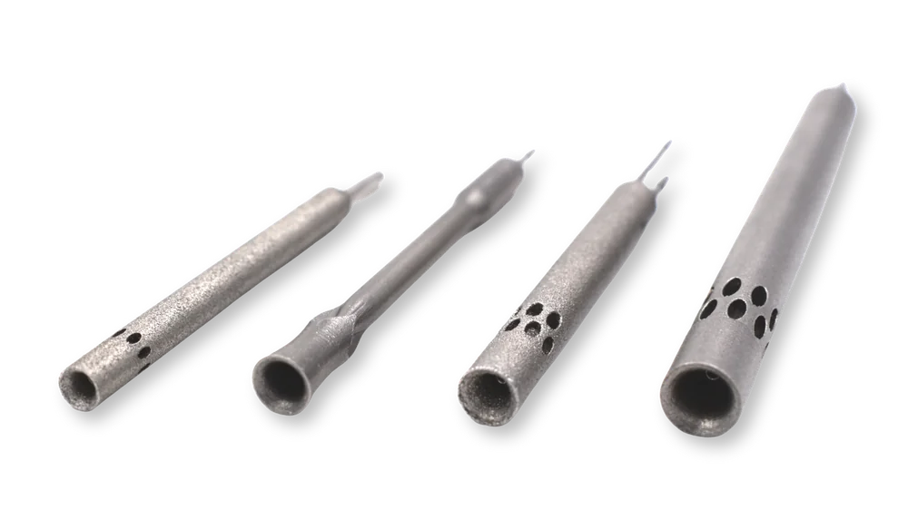
Multi-hole probes address part of this. A 5-hole probe resolves total pressure, static pressure, and flow angle in yaw and pitch from a single probe tip, which gives the air data computation the angle-of-attack and sideslip inputs it needs. Kiel probes hold total pressure accuracy to ±50° of flow angle, compared to the roughly ±5° that a standard pitot tolerates.
Measurement hardware from K-Tec Systems
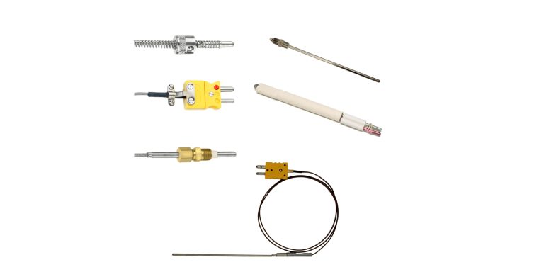
K-Tec Systems is an authorized U.S. distributor for Aerosensor, Vectoflow, and Surrey Sensors. Between them, we can match a probe to your platform, whether that is a 5-hole probe, a Kiel probe, or a yaw pitot for UAS, flight test, or wind tunnel work. We also manufacture custom thermocouples and RTDs that can be integrated directly into those probes, so the temperature input to your air data calculation comes from a sensor built for that location.
To discuss an air data measurement configuration for a UAS, flight test, or wind tunnel program, contact us at 248-414-4100 or contact@k-tecsystems.com.