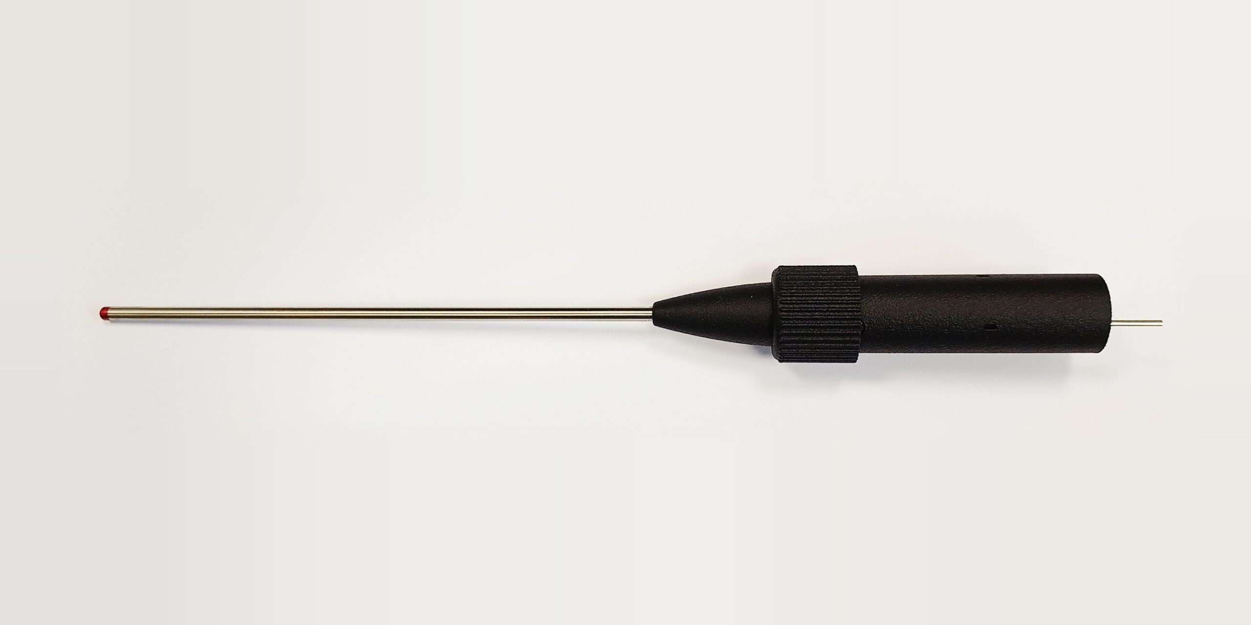
What Is a Pitot Tube and How Does It Work?
A pitot tube is a pressure-sensing probe that measures the total pressure of a moving fluid. Pointed directly into the flow, it brings the air arriving at its open tip to rest, and the pressure that builds up at that stagnation point is the total pressure. Combined with a separate measurement of static pressure, it yields the dynamic pressure of the flow and, from that, the velocity.
The device is named for Henri Pitot, who used the principle to measure river flow in the 18th century. The same physics now measures airspeed on aircraft, velocity in wind tunnels, and flow in ducts, engine inlets, and exhaust streams.
The three pressures
Understanding a pitot tube means keeping three pressures straight.
Static pressure is the pressure of the fluid at rest relative to the flow. It is the ambient pressure you would measure with a sensor moving along with the air. On an aircraft, it is sensed through a static port, a flush opening on the fuselage side positioned where the local flow is close to undisturbed.
Dynamic pressure is the pressure associated with the fluid’s motion. It equals one-half the density times the velocity squared, written as q = ½ρV². It is not something you can sense directly with a single port; it is the difference between the other two. For how this is measured in practice, see How Dynamic Pressure Is Measured in Vehicle Wind Tunnels.
Total pressure, also called stagnation pressure, is the sum of static and dynamic pressure. NASA Glenn Research Center states the relationship as ps + ½ρu² = pt. It is the pressure the fluid would have if brought to rest without loss, and it is what the pitot tube’s forward-facing opening senses.
How a pitot tube works
The open tip of the tube faces upstream. Air enters the tube and, because the tube is closed at the other end except for the connection to a pressure sensor, the air inside comes to rest. At that stagnation point, all of the flow’s kinetic energy has been converted to pressure, so the sensor reads total pressure.
A static port, either on the side of the same probe (a pitot-static tube) or elsewhere on the body, senses static pressure. A differential pressure transducer connected between the two reads dynamic pressure directly.
From dynamic pressure, velocity follows. NASA Glenn gives the expression as V = √(2(pt − ps)/ρ), where ρ is the fluid density. This is derived from Bernoulli’s equation and holds for incompressible flow, which in air means low subsonic speeds. At higher Mach numbers, a compressibility correction is applied.
What density has to do with it
Velocity depends on density, and density depends on static pressure and temperature. A pitot-static system alone gives dynamic pressure; it does not give velocity until density is known. An aircraft airspeed indicator solves this by assuming sea-level standard density, which is why it displays indicated airspeed rather than true airspeed. The conversion is covered in How to Calculate True Airspeed from Pitot-Static Data.
In a wind tunnel or a test cell, the facility’s own pressure and temperature sensors supply density. This makes the temperature sensor part of the velocity measurement. An error in the air temperature reading propagates directly into the computed velocity.
Limitations of a standard pitot tube
A conventional pitot tube reads total pressure accurately only when it is aligned with the flow. Beyond roughly ±5° of misalignment, the tip no longer captures a clean stagnation point and the reading falls off. In a wind tunnel wake, behind a wing, or on a vehicle in a crosswind, the flow angle can easily exceed that.
The tube also tells you nothing about flow direction. It reports a scalar pressure, not a vector. It reads low at very low velocities, where dynamic pressure is small relative to sensor resolution. It can be blocked by ice, water, or debris, which is a well-known failure mode in aviation.
Probes that extend the pitot principle
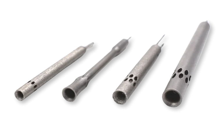
Kiel probes surround the total pressure tube with a shroud that realigns incoming flow with the internal tube. This extends accurate total pressure measurement to flow angles of up to roughly ±50°, depending on design, which is why Kiel probes are used in engine exhaust, behind rotating machinery, and anywhere the flow direction is uncertain.
Yaw pitots measure dynamic pressure and yaw angle simultaneously. On a road vehicle or race car, ambient wind produces yaw angles that reach double digits, and aerodynamic loads change strongly with yaw. Without measuring it, road data cannot be correlated back to tunnel or CFD results.
Multi-hole probes use five or more pressure ports arranged around the tip to resolve the full flow vector: total pressure, static pressure, and flow angle in both yaw and pitch, from a single probe.
Kiel rakes array many Kiel probe tips across a defined area for simultaneous multi-point total pressure measurement, which is how boundary layers, jet exhaust profiles, and wake surveys are mapped. For a broader look at how these probes are used in test facilities, see Flow Probes and Aerodynamic Measurement in Wind Tunnel Testing.
Pitot and flow probes from K-Tec Systems
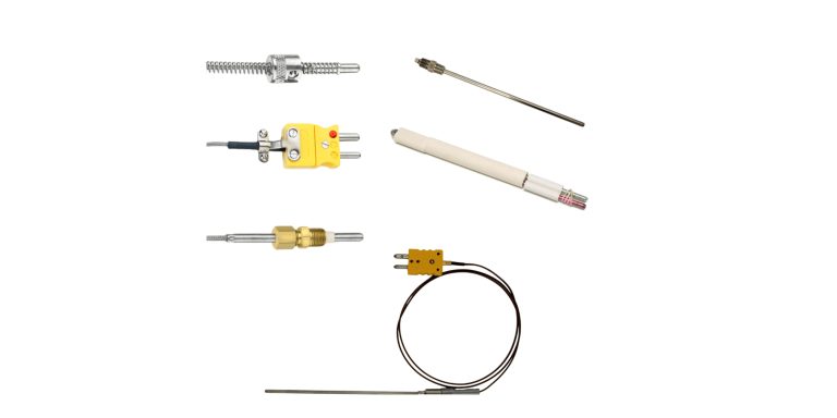
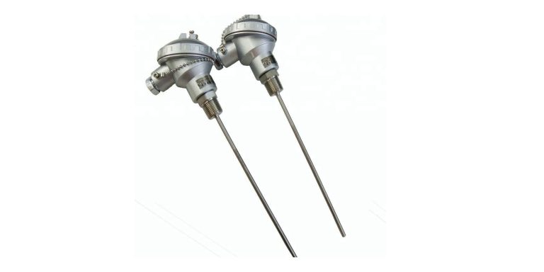
K-Tec Systems is an authorized U.S. distributor of aerodynamic flow probes, including pitot probes, yaw pitots, Kiel probes, Kiel rakes, and 5-hole probes for aerospace, automotive, and uncrewed air system testing. K-Tec also manufactures custom thermocouples and RTDs, so the temperature measurement that feeds a velocity calculation can come from the same supplier as the pressure measurement.
To discuss a pitot or multi-hole probe configuration for wind tunnel, UAS, or vehicle testing, contact us at 248-414-4100 or contact@k-tecsystems.com.